Cowan Dynamics
This article has been reviewed by Cowan Dynamics Application Engineering team. Contact Us and our application engineers will assist you with your application.
A pneumatic actuator is a device that converts compressed air into mechanical motion, enabling automation in industrial applications. It is commonly used in industries, including manufacturing, automotive, mining, and oil & gas. These actuators are valued for their reliability, cost-effectiveness, and ease of maintenance.
Whether you need linear motion or rotary motion, selecting the right actuator is essential for efficiency, longevity, and reliability. This guide will walk you through everything you need to know about pneumatic actuators, their types, applications, and how to choose the right one for your needs.
How Do Pneumatic Actuators Work?
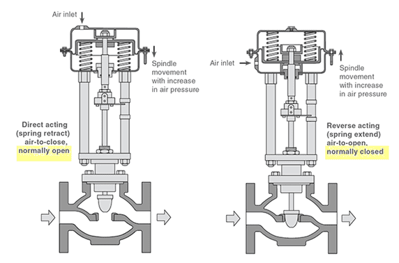
The working principle of a pneumatic actuator involves using compressed air to move a piston inside a cylinder. The pressure forces the piston to move, generating linear or rotary motion. This movement can be controlled for precise movement in automation systems.
Compressed air entering one side of the cylinder pushes the piston forward, generating linear motion. The expelled air exits through an exhaust port. In double-acting actuators, compressed air is supplied alternately to both sides of the piston, allowing controlled back-and-forth movement for greater precision.
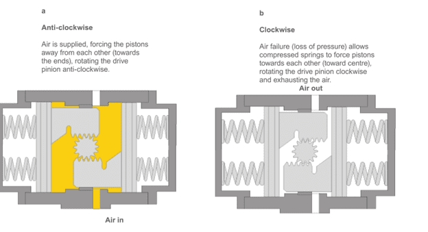
For rotary pneumatic actuators, the piston inside is connected to a rack-and-pinion mechanism or a vane-style design, which converts the linear motion into rotational motion. These are commonly used in applications requiring controlled rotary motion, such as butterfly valves and robotic automation.
The efficiency of a pneumatic actuator depends on the air pressure supplied, the quality of seals, and the design of the cylinder. Regular maintenance, such as checking for leaks and ensuring proper lubrication, helps maintain optimal performance and extends the lifespan of the actuator.
Types of Pneumatic Actuators
There are two primary types of pneumatic actuators:
Pneumatic Linear Actuators
These pneumatic linear actuators provide straight line movement. Linear actuators convert air into linear motion, either extending and retracting or pushing and pulling a load. They are typically used in applications where components need to be moved in a single direction, making them essential in material handling, automation, and heavy industrial processes.
Ideal for applications requiring linear movement, such as knife gate balves used in slurry and ore transport pipelines to regulate abrasive materials.
Pneumatic Rotary Actuators
Rotary pneumatic actuators convert air into rotary motion, making them ideal for applications where components need to turn, rotate, or pivot. They provide a fixed or adjustable angular displacement, making them essential for valve automation, assembly lines, and robotic applications.
These rotary actuators are commonly used in butterfly valves and industrial automation.
Where Are Pneumatic Actuators Used?
Pneumatic actuators play a vital role in heavy industries like mining, oil and gas, and power generation, where reliability, safety, and efficiency are crucial. These actuators are widely used to operate valves, dampers, conveyors, and process control equipment in harsh environments where electrical systems may not be suitable due to explosion risks or extreme conditions.
Mining Industry

In mining operations, pneumatic actuators are used in various equipment to control material flow, safety mechanisms, and automation systems. Their resistance to dust, moisture, and vibrations makes them an ideal choice for mining applications.
-
Slurry Valves: Valve actuators for knife gate, or ball valves for handling abrasive slurries in ore processing.
-
Water Control Valves: Used in dewatering systems to regulate water discharge from underground or open-pit mines.
-
Dust Suppression Systems: Control spray nozzles for dust management at conveyor belts and crushers.
Oil & Gas Industry Applications
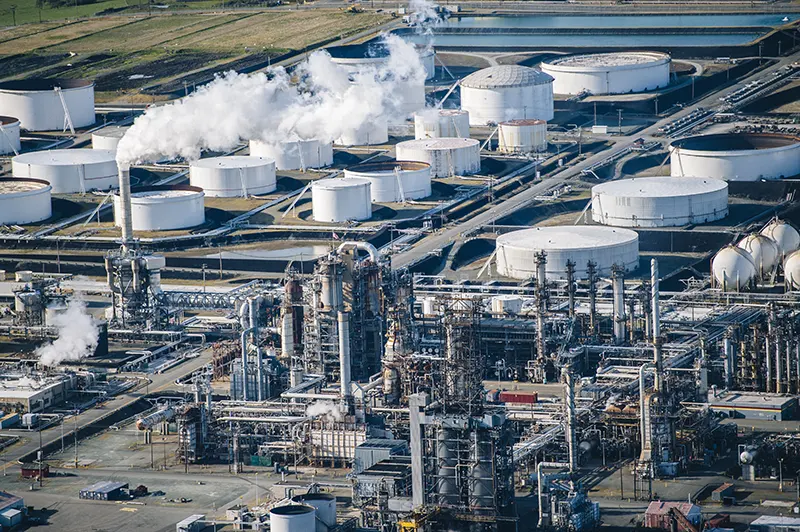
Pneumatic actuators are extensively used in offshore and onshore oil & gas operations due to their reliability in hazardous (explosive) environments and ability to function without electrical power.
-
Wellhead Control Valves: Control the flow of crude oil and natural gas from production wells.
-
Pipeline Block & Bleed Valves: Operate in pipeline isolation systems to prevent leaks and pressure buildup.
-
Emergency Shutdown Valves (ESD): Provide automatic shutdown in case of gas leaks, overpressure, or equipment failure.
-
Blowout Preventers (BOPs): Critical in drilling operations, pneumatic actuators rapidly close the BOP to prevent blowouts.
Automotive Assembly Lines
Pneumatic actuators are widely used in automotive production for their speed and reliability in repetitive operations. Key applications include:
-
Welding operations – Controlling robotic welding arms, clamps, and positioning devices.
-
Conveyor control – Moving chassis, engine components, and body panels along the production line.
-
Pressing and stamping – Operating sheet metal forming presses.
-
Door and panel assembly – Aligning and securing car doors, fenders, and hoods.
-
Painting and coating systems – Actuating spray nozzles for consistent application of paint.
-
Tire and wheel assembly – Positioning wheels and tightening lug nuts in automated mounting stations.
Key Factors to Consider When Choosing a Pneumatic Actuator
When selecting a pneumatic actuator, consider the following factors:
-
Operating pressure: Most systems operate between 4–8 bar.
-
Load capacity: Choose an actuator that can handle heavy loads.
-
Speed and stroke length: Consider the required travel distance.
-
Mounting requirements: Ensure compatibility with your existing setup.
Double Acting vs. Single Acting Pneumatic Cylinders
There are 2 types of cylinders:
Single-acting pneumatic cylinders: Use compressed air to move the piston in one direction. Single acting actuators rely on a spring for return motion and are suitable for simpler tasks.
Double-acting pneumatic cylinders: use air pressure to extend and retract the piston, providing better control and efficiency.Double-acting cylinders: Utilize air pressure to move the piston in both directions.
Maintenance & Repairs of Pneumatic Actuators
To ensure longevity, follow these maintenance tips:
-
Regularly check for air leaks.
-
Lubricate moving parts to reduce wear.
-
Inspect the flexible diaphragm and seals for damage.
-
Replace worn-out valves and pistons.
Example failures if not properly maintained:
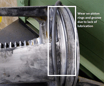
Wear on piston rings and groove due to lack of lubrication:
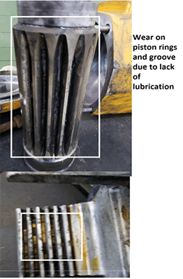
Wear on rack and pinion due to lack of lubrication:
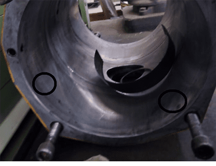
Hollow cylinder of pneumatic actuator showing signs of wear:
What to Look for in a Quality Pneumatic Actuator
A good pneumatic actuator should have:
-
High-quality piston inside a durable cylinder.
-
Corrosion-resistant materials.
-
Precise control over linear motion and rotary motion.
-
Compatibility with your existing valves.
Comparing Pneumatic and Hydraulic Cylinders
Pneumatic actuators use compressed air, while hydraulic cylinders use fluid. Pneumatics are faster and cleaner, making them suitable for food processing, whereas hydraulics are better for heavy loads.
Rotary Pneumatic Actuators and Their Applications
Rotary pneumatic actuators convert compressed air into rotational motion. They are ideal for:
-
Butterfly valves
-
Robotic arms
-
Packaging systems
|
Factor |
Application |
Recommendation |
|
Type of motion |
Globe valve / gate valve |
Linear motion actuator |
|
Butterfly valve / ball valve |
Rotary motion actuator |
|
|
Required control |
Open / close valve position, isolation, or shutoff valves |
Spring loaded single acting actuator for shutoff valves that need a failsafe action or double acting for non-critical isolation valves |
|
Continuous variable valve position, control or modulation applications |
Most commonly Dual port double acting actuator, single acting if a failsafe position is needed. High duty cycle |
|
|
Torque |
Liner along opening / closing movement |
Rack and pinion actuator |
|
High torque on start and end of motion |
Scotch-yoke actuator |
|
We Can Help You Choose the Right Pneumatic Actuator
Selecting the right pneumatic actuator involves understanding your application’s needs, pressure requirements, and load capacity. By considering linear or rotary movement, valves, and pistons, you can optimize performance and efficiency.
Our application engineers can confidently help you choose the best pneumatic actuator for your industrial applications, ensuring smooth and efficient operation for years to come.