Cowan Dynamics
This article has been reviewed by Cowan Dynamics Application Engineering team. Contact Us and our application engineers will assist you with your application.
Valve Automation Overview
Industrial valves are flow control devices that are used in pipelines and process plants. The valve’s job is somewhat like that of a tap where the flow of the pipeline is controlled by opening or closing the valve. Valve Automation is the process of adding a valve actuator and control system to the valve. Actuators could be powered by human, electric, pneumatic or hydraulic energy.
Valve Automation Centers Need the CPAC
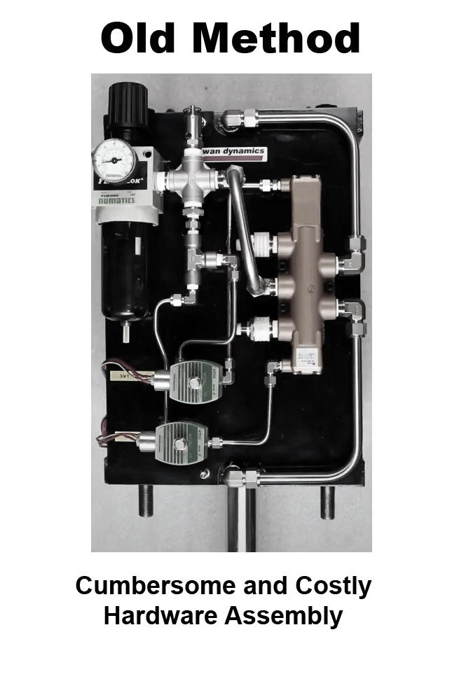
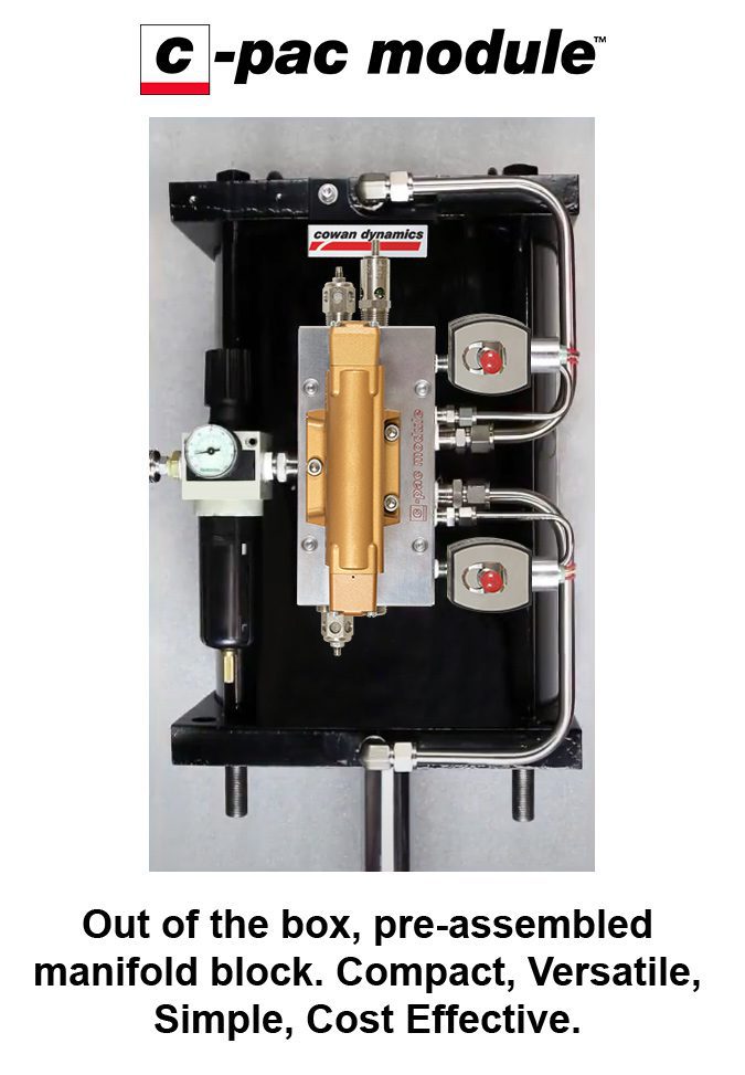
Custom valve automation is a time-consuming and expensive task compared to integrating our off-the-shelf CPAC pneumatic manifold. Save up to 25% by eliminating costly and cumbersome piping, fittings, & panels with our all-in-one C-PAC Module.
Valve Automation Types
1. Manual
When a valve uses manual energy, it is operated by hand using hand-wheels, levers and gears. Although they aren’t as expensive as the other options and can be easy to operate, it isn’t always possible or ideal to use this method. Larger valves can be impossible to operate manually due to high thrust requirements and other valves can be located in remote or hazardous environments. It can also be a safety issue if the valve needs to be closed faster than can be done by hand.
2. Pneumatic
Pneumatic valve actuators use air pressure, or another gas, as its power source. With its simplistic design, they require minimal maintenance and are used in applications where there are temperature extremes.
Failure action in pneumatic systems
When referring to failure in valve control systems we often hear the terms Fail Open, Fail Close and Fail in last position. These refer to the position the valve should take in the event of a failure, to understand what happens in the event of a failure we must first define types of failures.
In a pneumatic valve automation system, 2 main types of failure can occur; When there is a failure in the signal to the controls, which is usually an electrical signal of low voltage e.g., electrical signal to the solenoids, this type of failure is known as loss of signal. When there is a failure in the source of energy used to move the valve actuator, which in the case of pneumatic systems is the pressurized gas, this is known as loss of power or loss of energy.
In the event of loss of signal, air can be routed to meet a “fail open” or “fail close” requirement or controls can be selected to trap the compressed gas in the actuator to achieve a “fail in last position”.
Single-acting pneumatic actuators
If the energy used to move the actuator is lost, a last position failure can be achieved; however, if opening or closing is needed after the failure, there is no energy to move the actuator and therefore the valve.
In these cases, an external source of energy is needed. The most common stored energy systems in valve automation are pre-compressed springs, also called single-acting actuators. When using these actuators, if a power failure occurs the spring loses resistance and actuates the valve to an open or close position depending on the configuration.
Air-spring fail-safe pneumatic actuators
For systems where a high amount of energy is needed such as high thrusts or torques valves, springs are no longer a practical option. In such cases, we use stored pressurized fluids which in the case of pneumatic systems are often called air-spring fail-safe systems. The idea behind these systems is to route this pressurized gas to move the actuator to an open or close position in the event of a loss of power or plant air supply pressure loss.
The pressurized air is stored in tanks or vessels, the size of these tanks will depend on the amount of air that is needed to be stored, which depends on the volume of air displaced by the actuator, the maximum air supply pressure and the minimum pressure required to operate the actuator. In systems where large volumes of air need to be stored, tanks can also reach large sizes. To solve this problem, we can resource to the use of pneumatic pressure boosters.
3. Hydraulic
Similar in operation to pneumatic actuators, hydraulic actuators convert fluid pressure into motion. Suited for high-force applications, they can produce forces greater than a pneumatic actuator of the same size. In some applications, the process fluid itself can provide the hydraulic pressure needed to operate the actuator.
4. Electric
The electric actuator converts electrical energy into torque to operate the valve. Offering the highest precision-control positioning, they are also quiet, non-toxic and energy efficient. However, they are expensive and not ideal for critical applications that require high speed or fail modes.
5. Boosters
Pneumatic pressure boosters
Pneumatic pressure boosters are a 100% mechanical equipment that, as their name suggests, are used to boost pneumatic pressure. When air at X pressure is introduced to the booster, the pressure activates the mechanical components of the booster and employing an internal piston that sections the booster into 2 volumes; the thrust and compression volumes, it increases the inlet pressure.
The thrust volume is the section that generates the thrust necessary to move the internal piston and compress the air in the compression volume. The compression volume is calculated depending on the ratio at which the pressure is to be amplified. For example, a 2:1 amplifier that will duplicate the inlet pressure will have a larger area than one with a 3:1 or 4:1 ratio. Once the piston reaches the end of the stroke the movement starts in the other direction, the booster will continue this cyclic motion until the pressure given by the ratio, either 2:1 3:1 or 4:1, is reached.
How do boosters work when used as part of valve automation failure systems?
The inlet of the booster is connected to the main airline and the outlet to a storage tank, as mentioned, when pressure enters the booster, it increases it according to its design ratio. For example, with a 4:1 booster and an inlet pressure of 60 psi-g we will have 240 psi-g output to the tank. The tank then stores the air at a pressure of 240 psi-g.
In normal operation, the regular plant air pressure supply can be used to operate the valve, if there is a failure on this main supply the pressurized air in the tank is used to operate the valve. It is important to note that due to the mechanical operation of the booster, as soon as the air pressure drops below the design set point, in this case 240 psi-g, the booster is activated once the regular pressure in the plant is available to boost the pressure back to 240 psi-g.
Because the air in the tank can be stored at a higher pressure thanks to the booster, the size of the tank and the actuator can be significantly reduced when using a pressure booster.
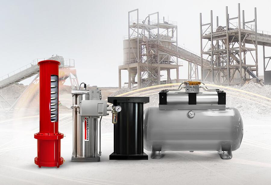
Valve actuators play a major part in automating process control. They can be designed to fail-open, fail-close or fail last. Found in all kinds of process plants, actuators are used in wastewater treatment plants, power plants, mining and nuclear processes, food factories, refineries, and pipelines. Focusing on the Oil & Gas, petrochemical, power generation, mining and aerospace Industries, Cowan offers a wide range of valve actuators designed for severe service.